Multi-terminal flat data cable puncture connection
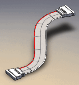
An insulation feedthrough connection (IDC), sometimes called an insulation feedthrough terminal (IDT), is a method of connecting wires to a connector or terminal without stripping the insulation. This method can also be used on wires without insulation. The puncture connection method has been recognized by the industry and is widely used in various types of connectors.

An important part of feedthrough connections is ensuring compatibility between wires, connectors and assembly processes. Such as wire specifications, wire-to-wire specifications (for multi-core flat or ribbon cables) IDC
Insulation thickness, type of insulation, processing methods used, or arrangement of cables and connectors can cause unreliable connections or electrical opens or shorts.
When making puncture connections to multi-terminal flat cable IDC, the following standards must be followed.

Acceptable - Level 1, 2, 3
(1) The cable end is flush with the outer edge of the connector or protrudes no more than twice the cable thickness and does not violate the minimum electrical clearance.
(2) There are slight machining marks, but there is no damage to the surface of the insulating material of the connector or cable.
(3) If a foldback is used, the inside of the cable should be flat against the connector body and not interfere with the mechanical installation of the connector.
(4) Unless otherwise noted, the colored reference bar (or starting numbered conductor) on the flat cable IDC is arranged in position 1.
Defect - Level 2,3
(1) The end of the IDC cable extends beyond the edge of the connector by more than twice the cable thickness. (See Figure 1-2)
Figure 1-2
(1) The connector’s gland latch is not fully latched.
(2) Any damage to the gland latch or barb.
(3) Not all wires in the cable extend into the IDC contacts.
(4) Exposed wires violate minimum electrical clearances.
(5) Folding back the cable, if applicable, will interfere with the mechanical assembly of the connector.
(6) The force-applying frame (gland) is installed in the opposite direction.
(7) Do not overlap the ribbon cable and the penetration terminal.
(8) The wires are too short and do not pass through the penetration terminal together.
(9) The colored reference strip (or starting number wire) on the flat cable is not arranged in position 1.
Learn More:Designing with Flexible Flat Cable


