What is RF Cable?
Radio frequency, referred to as RF Cable, is the abbreviation for high-frequency alternating electromagnetic waves. Electromagnetic waves are actually a relatively familiar concept.
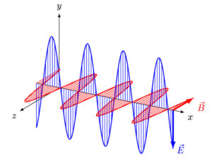
The figure below can roughly reflect this process. E represents the electric field and B represents the magnetic field. The phase and amplitude of the electric and magnetic fields at the same position on the axis will change with time.
Generally, radio frequency (RF) is the general term for electromagnetic waves with an oscillation frequency between 300KHz and 300GHz, and is widely used in radar and wireless communications.
2. Basic characteristics of radio frequency
In order to describe a given radio frequency signal, we can start from four perspectives: frequency, wavelength, amplitude, and phase.
2.1 Frequency and wavelength
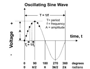
The frequency of electromagnetic waves is the frequency of electromagnetic field oscillation. Waves have cycles, and frequency (f) is the number of cycles the wave occurs in a given unit of time, measured in Hertz (Hz). The figure below shows the waveform per unit time of a signal with a frequency of 10Hz.
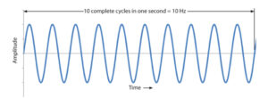
The wavelength (λ) is the distance that the wave propagates in one cycle. When the propagation speed is constant, the wavelength is inversely proportional to the frequency, that is, λ = c / f.
RFs of similar frequencies will interfere with each other, so there are organizations that specialize in spectrum management to allocate frequency bands to avoid mutual interference between applications and regulate the use of RF.
Due to attenuation and other factors, low-frequency electromagnetic waves can generally propagate longer distances than high-frequency electromagnetic waves, so they are often used in over-the-horizon radar. High-frequency electromagnetic waves have high energy, strong penetrating ability, and higher bandwidth.
They are now also used in some line-of-sight communications to alleviate the problem of low-frequency band congestion, such as mmWave communications.
2.2 Amplitude
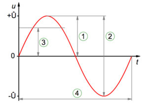
The amplitude signal of RF is a measure of the change in electric field oscillation within a single cycle. For a sine wave, it can be expressed by peak value ①, peak-peak value ②, and root mean square value ③.
2.3 Phase
Phase is the position at a single point in time in the wave cycle, usually expressed in radians in a sine wave.
3. Modulation
Pure electromagnetic waves are meaningless. In order to achieve the purpose of communication, we need to perform some operations on the electromagnetic waves at the transmitter to achieve the purpose of carrying data. This operation is called modulation. A little more academically, in order to achieve the purpose of communication, RF signals must have a way of carrying information. Modulation uses three wave characteristics (frequency, phase, amplitude) to modify the RF signal and transmit data.
Modulation is divided into analog modulation and digital modulation, which are introduced below.
3.1 Analog modulation
Analog modulation involves sending an analog digital signal with an analog carrier wave. The simplest analog modulation includes amplitude modulation (amplitude), frequency modulation (frequency), and phase modulation (phase).
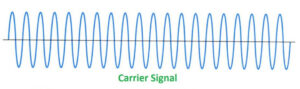
Carrier Wave: A waveform, usually a sine wave, that is modulated to transmit a signal.
original signal:

Amplitude modulation (AM): Basic amplitude modulation process: the modulation signal is added to the maximum amplitude of the carrier, and then multiplied by the carrier. The result is as follows:

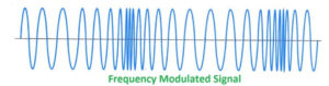
Direct frequency modulation: Use modulation signals to directly control the oscillation frequency of the oscillator.
Indirect frequency modulation: Now integrate the modulated signal, then phase-modulate the carrier, and finally obtain the final modulated signal through n times frequency multiplier. Frequency modulation can be obtained indirectly through phase modulation.
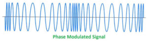
Phase Modulation (PM):
Like indirect frequency modulation, phase modulation and frequency modulation often occur together. By modulating the data signal, the phase of the carrier wave can be shifted forward or backward.
3.2 Digital modulation
Digital modulation refers to using digital signals to modulate sine or cosine high-frequency oscillations. The most basic modulation methods include: amplitude keying (ASK), frequency keying (FSK), and phase shift keying (PSK).
Anti-interference ability: PSK>FSK>ASK
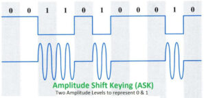
Amplitude Keying (ASK):
Controlled with a digitally modulated signal, either by changing the amplitude itself, or by simply turning the signal off and on to form an energy pulse (on/off key: OOK).
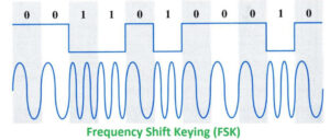
Frequency keying (FSK):
FSK modulates the frequency of a carrier wave with binary data, forming a significantly changing frequency to represent the data bits.
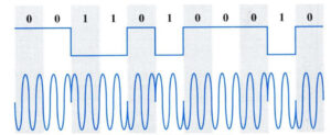
Phase shift keying (PSK):
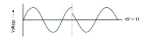
Use the positive and negative of the digital modulation signal to control the carrier phase. For example, when the amplitude of the digital signal is positive, the starting phase of the carrier is 180°, and when it is negative, the phase is 0°.
In high-speed systems, it is very slow to transmit digital data in the format of symbols representing a single 1 or 0. In order to increase the speed of data transmission, more complex modulation forms need to be borrowed to represent several bits with a single symbol.
Quadrature phase shift keying (QPSK):
also known as four-phase phase shift keying, uses four different phase differences of the carrier to represent the input,
and specifies four carrier phases of 45°/135°/225°/275°, each Phase represents the combination of two bits, as shown in the figure.

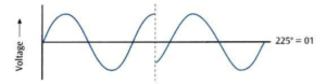

It is also easy to expand. By adding more phase points, more symbols can be generated and the data rate can be increased.
In addition to adding phase points, amplitude modulation can also be added to further increase the dimension of data representation and increase the efficiency of data transmission.
Quadrature Amplitude Modulation (QAM):
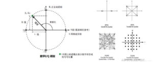
During the modulation process, the amplitude and phase of the carrier signal are used to represent different bit codes at the same time. The multi-ary system is combined with orthogonal carrier technology to further improve frequency band utilization. The picture below is an example diagram of 16-QAM.
For digital modulation, discrete digital quantities are used to control changes in carrier phase and amplitude, so its state on polar coordinates is represented as discrete points. These points form different patterns according to different modulation methods. , these patterns are sometimes called constellations. The picture above is the constellation diagram of 16-QAM.
I\Q modulation technology
All the digital modulation methods mentioned above are basically implemented through I\Q modulation (see Understanding I/Q Signals and Quadrature Modulation for how to implement it), I is in-phase (in-phase), q is quadrature (quadrature) ). IQ modulation means that the data is divided into two channels and carrier modulation is performed respectively. The two carriers are orthogonal to each other (the phase difference is 90°).
Digital IQ modulation completes the mapping of symbols to vector coordinate systems. The mapping points are generally called constellation points and have real and imaginary parts. This vector coordinate system can also be called the IQ coordinate system.
In the IQ coordinate system, any point determines a vector, which can be written in the form of (I + jQ). After digital modulation is completed, the corresponding I and Q waveforms can be obtained, so digital modulation is also called vector modulation.
The above figure shows the constellation diagrams of BPSK, QPSK, 16-QAM, and 32-QAM. Generally speaking, the data content carried by each state of a signal on the constellation diagram is called a symbol. Each symbol corresponds to a state on the constellation diagram. The rate of change between different states is called the symbol rate. ), sometimes also called baud rate.
4. Spread spectrum
Spread Spectrum (SS) is a communication technology that breaks up the spectrum of a transmitted signal to be wider than its original bandwidth. It is commonly used in the field of wireless communications. Spread spectrum has the following advantages:
① It is immune to various types of noise such as multipath distortion;
② It can be used to hide and encrypt signals. The receiver must know the spreading code to recover the original signal;
③ Multiple users can independently use the same higher bandwidth with almost no interference.
The two current mainstream spread spectrum technologies are frequency hopping spread spectrum and direct sequence spread spectrum.
4.1 Frequency hopping spread spectrum (FHSS)
A certain spreading code sequence is used to select multi-frequency frequency shift keying modulation,
so that the carrier frequency continuously jumps.
The sender broadcasts information in a seemingly random sequence of radio frequencies,
jumping from one frequency to another at regular intervals, and the receiver jumps frequencies simultaneously as it receives.
4.2 Direct sequence spread spectrum (DSSS)
A high code rate spreading code sequence is used to directly spread the signal spectrum at the sender, while the receiver uses the same spreading code sequence for despreading.
Learn More:RF Coaxial Cable – Overview of Cable Construction Elements